RTDs Explained
An RTD (Resistance Temperature Detector) is a temperature sensor that uses electrical resistance to indicate temperature. Certain metals display a characteristic and well-defined change in electrical resistance that corresponds to a change in temperature. By measuring the resistance of a known metal, the temperature can be calculated based on known response curves. RTDs are manufactured by placing a precise amount of metal onto a ceramic base in a thin film or wound wire format. By passing a small, precise current, typically 1mA, through the RTD and measuring the corresponding resistance, the temperature can be calculated.


Types of RTDs
RTD’s are categorized into different groups based on the resistivity of the metal used inside. Most modern industrial RTD’s use platinum as the resistive metal due to its inherent stability, temperature range and regularity of its temperature curve. Reotemp also offers less common RTD types such as nickel or copper to match and replace legacy and niche sensors.
| RTD TOLERANCE CLASSES |
||||
|---|---|---|---|---|
| Tolerance Class | Operating Range °C | Tolerance Range °C | Tolerance Values °C | Reotemp Code |
| B | -200 to +600 | -200 to +600 | ± (0.3 + 0.005 | t | ) | PX |
| A | -200 to +600 | -30 to +300* | ± (0.15 + 0.002 | t | ) | PA |
| AA | -200 to +600 | 0 to +150* | ± (0.1 + 0.0017 | t | ) | PD |
| 1/10 B | -200 to +600 | 0 to +50* | ± (0.03 + 0.0005 | t | ) | PE |
| *Class B tolerance for rest of operating range. | ||||
Platinum RTDs are offered with various classes/accuracy tolerance values. These classes are specified in IEC 60751 and ASTM E1137. Please see the RTD Tolerance Classes table on this page for the typical platinum RTD tolerance classes.
| ACCURACY COMPARISON: CLASS A VS B | ||
|---|---|---|
| Temperature °C | Class A RTD °C | Class B RTD °C |
| -190 | 1.25 | 1.25 |
| -100 | 0.80 | 0.80 |
| -50 | 0.55 | 0.55 |
| 0 | 0.15 | 0.30 |
| 50 | 0.25 | 0.55 |
| 100 | 0.35 | 0.80 |
| 200 | 0.55 | 1.30 |
| 300 | 0.75 | 1.80 |
| 500 | 2.80 | 2.80 |
RTDs vs. Thermocouples
The primary reason RTDs are chosen over thermocouples is their superior accuracy.
RTD vs. Thermocouple – Range, Accuracy, Durability, Response Time
Two of the most common methods of electrical temperature measurement are Resistance Temperature Detectors (RTDs) and Thermocouples. This video summarizes some of the differences in temperature range, accuracy, durability, and response time between RTDs and Thermocouples.
| ACCURACY COMPARISON: THERMOCOUPLE VS RTD | ||
|---|---|---|
| Type K Thermocouple | Class B RTD | |
| 32°F (0°C) | ± 3.96°F (2.2°C) | ± 0.54°F (0.3°C) |
| 392°F (200°C) | ± 3.96°F (2.2°C) | ± 2.34°F (1.3°C) |
- RTDs offer better stability with less temperature drift over time as they age versus thermocouples. Less temperature drift results in a longer service life and more accurate data.
- RTDs are also a better choice for low temperature applications as they have much better accuracies below 0°C. At temperatures below 0°C, thermocouples are less stable and less reliable.
- RTDs offer better repeatability. When temperature moves from a point and then returns, RTDs return much closer to the original point.
- RTDs offer greater interchangeability. When replacing or swapping sensors, the match between each sensor is much closer.
- In cases where long lead wires are required, RTDs are often recommended. This is because thermocouples require a more expensive lead wire consisting of the same metal as the thermocouple sensor. With RTDs, only common copper hook up wire is needed.
Accuracy
RTD Accuracy – Comparing Class A, B, AA, and 1/10B
A common misconception is that RTD accuracies are a fixed percentage across the board. This is not true. The accuracy of an RTD varies with temperature. To find the accuracy of an RTD, a formula is used to calculate the accuracy at a specific temperature point. Reotemp offers platinum RTDs that conform to internationally recognized classes. For each class, a different formula is used to calculate the accuracy at the specified temperature. These standards specify the accuracy formulas for an industrial platinum RTD. For customers who require a higher accuracy than offered in the B, A or AA classes, Reotemp offers 1/10 B RTDs. 1/10 B RTDs are 10 times more accurate than class B RTDs.
Operating Temperature Range
Reotemp RTDs are typically offered in two versions of operating temperature ranges. The chart below shows the operating ranges of standard and extended temperature RTDs. Choose the extended temperature option when the application requires high temperature exposure.
| RTD TEMPERATURE LIMITS | ||
|---|---|---|
| RTD Type | Minimum Limit | Maximum Limit |
| Reotemp Standard RTD Range | -328°F (-200°C) | 400°F (204°C) |
| Reotemp Extended Temp |
-328°F (-200°C) | 1112°F (600°C) |
RTD Failure Modes Explained
RTDs are extremely reliable temperature sensors. However, when they do fail, the failure modes can be typically broken down into the following categories:
Excessive Temperature
When RTDs exceed their designed temperature limits, the wire insulation materials in the stem will start to break down. This can result in electrical shorts and resistance errors. It can also create pinholes in the stem and cracks in the potting sealing the stem. When the stem integrity is breached, moisture can then get in and cause resistance errors.
Corrosion
Corrosion will often result in pinholes and pits in the stem. Once the stem is no longer sealed, moisture and the process can penetrate the stem causing resistance errors and electrical shorts. Some solutions to corrosion include thermowells or Teflon coated stems.
Extreme Vibration
Extreme vibration fatigues and strains wires and welded connections inside the sensor assembly. This can result in resistance errors as well as connection breaks. Reotemp’s solution to this failure mode is the unique Hi-Vibe™ option for vibration applications.
User Abuse
Some examples of user abuse include wires shorted out from being twisted together or corrosive media being allowed into the RTD assembly head.
Wire Configurations of RTDs
2 wire, 3 wire and 4 wire RTD Explained
A Resistance Temperature Detector (RTD) is a temperature measurement device that accurately uses resistance to measure temperature. Learn the differences between 2-wire, 3-wire, and 4-wire RTD’s and which one you should choose for your measurement needs.
2-Wire
2-wire configurations are the most basic, and offer no lead wire compensation. This means that the resistance of the lead wire is added to the resistance of the RTD element which makes the measured temperature appear higher than the actual temperature. While the influence of lead wire resistance is minimal for short runs, longer lead wire results in a higher discrepancy.
3-Wire
A 3-wire configuration uses the third wire to sample lead wire resistance and subtract it from the measurement circuit. This is the most common configuration for industrial applications and provides adequate compensation for lead wire resistance.
4-Wire
A 4-wire configuration fully isolates the resistance of the RTD element from the resistance of the lead wire and is recommended for applications requiring the highest accuracy.
RTD Response Time
The diameter of the RTD probe will affect the response time of an RTD, as shown in the RTD Typical Response Times chart on this page. If response time is critical, consider using the smallest diameter probe which still meets the application requirements.
RTD Response Time
Wire Length Guide
Actual maximum lead wire length is dictated by total loop resistance and the presence of electrical noise. Allowable loop resistance is dictated by the equipment used to measure the sensor’s signal. The tables below have been generated using assumptions of allowable loop resistance. Final determination of suitability rests with the customer. Green zones indicate estimated lead wire lengths that will allow the temperature sensor to still function properly with limited accuracy loss. The exact accuracy loss is dependent on a number of application specific factors.

How long can RTD lead wire be? How long can thermocouple lead wire be? What about 4-20mA transmitter lead wire? Find out in this video.
Hazardous Locations or Applications
Safety is a primary concern when instruments are used in hazardous locations, especially in applications where the potential for explosion is involved due to a concentration of flammable gases, vapors or dust. When specifying a sensor or any instrumentation circuit for use in a hazardous location, the user needs to exercise caution in complying with local and/or national electrical codes and safety regulations.
It is important to consider the failure modes of the instrumentation and any catastrophic effects these modes could have based on the environment they are used in. The integrity and suitability of any instrumentation for use in hazardous locations is ultimately the responsibility of the end user and/or of those making the specification decisions.
Generally, when instrumentation is to be used in a hazardous location, two commonly used methods to minimize the risk of ignitions and explosions are intrinsically safe and explosion-proof systems. Intrinsically safe systems are centered around prevention whereas explosion proof systems are focused on containment.
Intrinsically safe systems operate on low power and are designed to limit the thermal and electrical energy of the instrument and associated connections to a level where ignition is not possible. Also, the devices cannot store enough energy to cause a spark when energy is released.
Explosion proof systems are based on the principle of containment. In other words, an explosion proof enclosure prevents any generated flames, sparks or hot gases from escaping. These devices are designed to contain, control, cool, and/or vent any possible ignition due to a failure mode, without igniting the surrounding atmosphere.
When it comes to RTDs and thermocouples, it is important to note that these temperature measurement sensors are defined as simple apparatus by the National Fire Protection Association (NFPA). This means that they simply operate on, store and/or generate too low level an energy, i.e. low amperage and low voltage, to cause an ignition. This status can change, however, depending on what the sensor is connected to or how hot the surface of the sensor assembly may get outside of the process. The required method of protection can vary depending on many different factors and the entire instrumentation system must be examined before use in hazardous locations.
In summary, RTD and thermocouple sensors are considered a simple apparatus as defined in the National Electric Code NFPA 70 Article 100 (Rev. 2020). By definition, these sensors generate too low an energy to be an ignition source. For use in hazardous environments, the sensor is typically connected to an intrinsically safe or explosion proof apparatus. Final application suitability and compliance with regional standards are to be determined and approved by the end user.
Reotemp Hi-Accuracy
When you need the highest possible accuracy…
Hi-Accuracy™ is an optional feature on many Reotemp RTD sensors. Reotemp uses specialized fixed point calibration cells to determine more precise coefficients for the specific sensor in your order. You will input these values into your transmitter to replace the generic values. Once the sensor-specific coefficients are entered, your sensor will typically be 5 times more accurate! Add this feature by selecting –AC in the options section of the RTD configurator.
The graph below shows the typical accuracy improvement for a temperature sensor system. Without the Hi-Accuracy option the temperature reading could potentially be off 1.15°C from the actual process value vs 0.28°C with Reotemp’s hi-accuracy option.


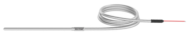
Reotemp Hi-Vibe™
![]()
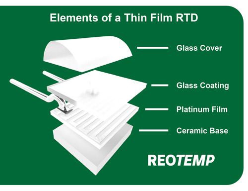
Hi-Vibe™ is an optional feature available on many Reotemp RTD sensors. Although thin film RTDs are very robust, vibration is a common cause of premature failure or drift in an RTD sensor. Reotemp’s Hi-Vibe construction is a proprietary design that reinforces welds and other weak points around the RTD to better withstand shock due to vibration. Hi-Vibe has been proven to significantly improve lifespan and help to maintain accuracy in high vibration environments.
Case Study: Turbine Test Cells
Customer: Major Turbine Manufacturer in Western US
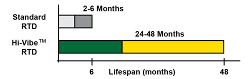
Problem: Sensors on turbine test cells were failing after a short period of time (2-6 months) causing maintenance downtime and excessive replacement costs. The RTDs were found to be failing due to the shock and resonance from the high frequency vibrations in turbine operation.
Solution: After several rounds of testing, Reotemp developed a stronger Hi-Vibe RTD construction that could better withstand the extremely harsh turbine test cell environment. The turbine manufacturer tested the new design for over a year with excellent results as shown in the chart below. Ongoing testing has shown the lifespan to be improved by a factor of 4-10 times versus the standard sensor. Ultimately, this turbine manufacturer switched all of their turbine RTD sensor requirements over to this Reotemp Hi-Vibe design for improved performance.
By reinforcing potential weak points in a standard RTD construction, the Hi-Vibe feature dramatically extends the life of a sensor under high vibration conditions. If your application is subject to vibration, the Hi-Vibe design is an excellent option to consider.
Benefits:
Design minimizes failure modes of vibration
Increases the life of your RTD up to 10x
Reduces frequent replacement cost due to vibration failure
Allows usage of RTDs in applications previously restricted to thermocouples
Improves process efficiency with higher accuracy RTDs
How to Order This Feature:
In the options section of the RTD part builder, use the -VB code.