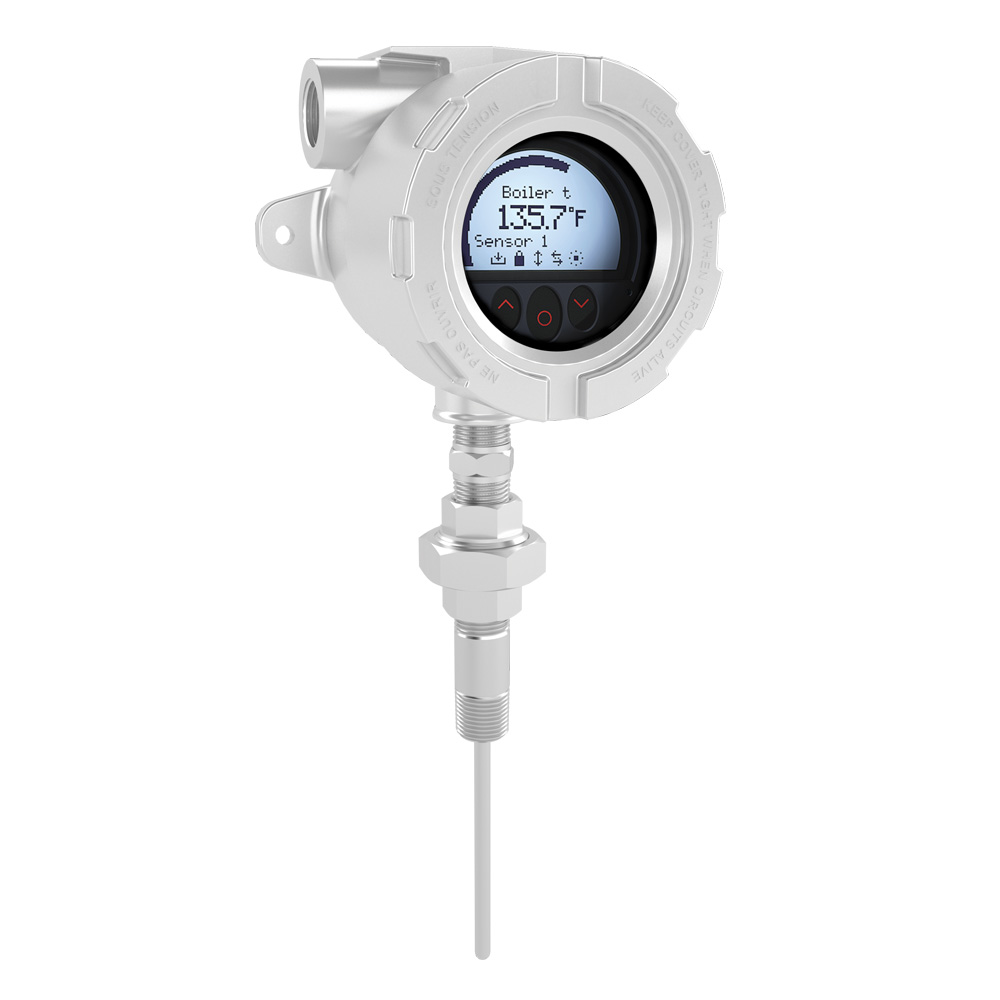
MODEL W FIELD MOUNTED HART TEMPERATURE TRANSMITTER
The REOTEMP Model W Explosion Proof Field Mounted HART Temperature Transmitter features a local display, HART compatibility, and a 4-20mA output. The field mounted transmitter is available as a complete RTD or thermocouple assembly customized to your process.
Key Features
- RTD or TC input, analog output
- High definition local operator interface (LOI) with 3 optical buttons
- Selectable red or white backlight
- Ex d explosion proof / flame proof aluminum head
- HART 7 functionality with HART 5 compatibility
High Definition Display
- 0, 90, 180, & 270 degree position adjustments
- Monitoring, programming and diagnostics view
- Extensive diagnostics with flashing red or white backlight
Local Operator Interface (LOI)
- 3 optical buttons; up, down and enter
- Dynamically adaptive to wear or accumulation of dirt
- Immune to interference from ambient light sources
- Useable with or without gloves
Configuration
- From the LOI through guided menu
- PReset and HART modem
- HHC, DCS or AMS via HART
Mounting / Installation
- For installation in zone 0, 1, 2 and zone 20, 21, 22 and in Class 1, Division 1 and 2 applications
- Hardware assessed for use in SIL 2 applications
- Mounting on 1.5”–2” pipe bracket or on wall / bulkhead
Application
- Linearized temperature measurement with TC and RTD sensors e.g. Pt100 and Ni100
- HART communication and 4…20 mA analog PV output for individual, difference or average temperature measurement of up to two RTD or TC input sensors
- Up to 63 transmitters (HART 7) can be connected in a multidrop communication setup
Technical Characteristics
- NAMUR NE43 and NE89
- HART protocol revision can be changed by user configuration to either HART 5 or HART 7 protocol
| Environmental Conditions | |
| Operating Temperature | -40°C to +85°C |
| Storage Temperature | -40°C to +85°C |
| Calibration Temperature | 20…28°C |
| Relative humidity | 0…100% RH (condensing) |
| Protection degree | IP54 / IP66 / IP68 / type 4X |
| Mechanical Specifications | |
| Dimensions | Ø 110 mm |
| Dimensions (HxWxD), aluminum | 109.3 x 145 x 126 mm |
| Weight approx. | 1.3kg |
| Wire size | 0.13 x1.5 mm2 / AWG 26…16 stranded wire |
| Screw terminal torque | 0.4 Nm |
| Vibration | IEC 60068-2-6 |
| 2…25 Hz | ±1.6 g |
| 25…100 Hz | ±4 g |
| Number of digits | 5 |
| Backlight | Selectable ON/OFF |
| Backlight color | Selectable white or red |
| Common Specifications | |
| Supply voltage, DC: Ex ia, intrinsically safe | 10 (12 – with backlight)…30 VDC |
| Supply voltage, DC: Other | 10 (12 – with backlight)…35 VDC |
| Isolation voltage, test / working | 1.5 kVAC / 50 VAC |
| Response time (programmable) | 1…60 s |
| Signal / noise ratio | > 60 dB |
| Programming | HART |
| Start-up time, transmitter to display | Max. 5 s |
| Long-term stability, better than | ±0.1% of span / year |
| Transmitter Accuracy | Better than 0.05% of selected range |
| Signal dynamics, input | 22 bit |
| Signal dynamics, output. | 16 bit |
| EMC immunity influence | < ±0.1% of span |
| Extended EMC immunity: NAMUR NE21, A criterion, burst | < ±1% of span |
| Max. offset. | 50% of selected max. value |
| Input Specifications | |
| RTD type | Pt50/100/200/500/1000; Ni50/100/120/1000 |
| Cable resistance per wire | 5 Ω (up to 50 Ω per wire is possible with reduced measurement accuracy) |
| Sensor current | Nom. 0.2 mA |
| Thermocouple type | B, E, J, K, N, R, S, T |
| Cold junction compensation (CJC) | Constant, internal or external via a Pt100 or Ni100 sensor |
| Output Specifications | |
| Signal range | 4…20 mA |
| Min. signal range | 16 mA |
| Load (@ current output) | ≤ (Vsupply – 10) / 0.023 [Ω] |
| Load resistance, with backlight | ≤ (Vsupply – 12) / 0.023 [Ω] |
| Sensor error indication | Programmable 3.5…23 mA |
| NAMUR NE43 Upscale/Downscale | 23 mA / 3.5 mA |
| Updating time | 440 ms |
| HART protocol revisions | HART 7 and HART 5 |
| Observed Authority Requirements | |
| EMC | 2014/30/EU |
| EAC | TR-CU 020/2011 |
| Approvals | |
| EU RO Mutual Recognition Type Approval | MRA0000009 |
| ATEX 2014/34/EU | DEKRA 15 ATEX 0058 X |
| IECEx | IECEx DEK 15.0039 X |
| FM | FM16US0009X / FM16CA0010X |
| CSA | 70024231 |
| EAC Ex TR-CU 012/2011 | RU C-DK.GB08.V.01316 |
| INMETRO | DEKRA 15.0014 X |
| NEPSI | GYJ15.1336X, GYJ15.1337X and GYJ15.1338X |
| SIL | Hardware assessed for use in SIL applications |
Download Drawing:
Download the Model W Manual: